on
Making Active Loudspeakers Using EqualizerAPO
I would like to bring up the topic of active crossovers. This is a very convenient thing that allows you to quickly change filter settings and try different configurations without soldering new crossovers. In addition, the sound quality of the active crossover is a bit higher than that of the passive crossover on average components - it gives a more predictable and a more transparent result.
For the active crossover, we can use external tools or software on our own computer.
In this post I will describe how to build an active crossover based on a normal Windows computer. We won’t need anything but a multi-channel sound card or multi-channel receiver. So this article is intended for those who want to try an active crossover, but don’t want to invest a lot of money in new equipment right away.
We will need:
- Windows PC (in my case mini-PC Intel NUC),
- Multi-channel receiver (multi-channel sound card also works),
- The EqualizerAPO software,
- Room EQ Wizard software,
- Notepad ++ app,
- Measurement microphone (in my case miniDSP UMIK-1) and a tripod.
In my opinion, a measuring microphone is a must when building loudspeakers. Without it, it will be difficult to check that everything is fine and to understand what’s wrong when you don’t like the game. There is no way to determine the delay of individual drivers without a microphone. So be sure to get yourself a calibrated microphone. This is a necessary expense to try active filters.
EqualizerAPO configuration for Windows
We download and install EqualizerAPO. This is a system component, so if you have 32-bit Windows, download the 32-bit version. But most have to download the 64-bit version:
https://sourceforge.net/projects/equalizerapo/files/1.2/
I recommend installing not in the Program Files folder, but in the root of the C:\ drive or in the “Documents” folder so that Windows does not disturb us from changing configuration files.
EqualizerAPO is an effects module (enhancement) for the Windows sound system. After installation, run the Configurator application.
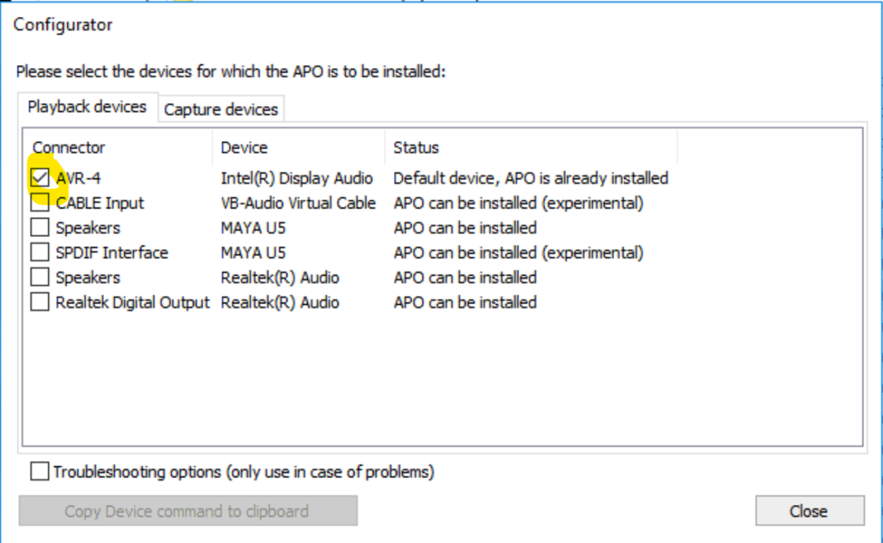
We choose our sound card. “APO will be installed” will appear in the Status field and the “Close” button will change to “Restart”. We press it and restart the computer. After re-enabling, we will be able to configure the sound processor.
You also need to enable multi-channel sound mode and audio track format. We open the Windows sound settings. Press the right mouse button and select “Speaker settings”:
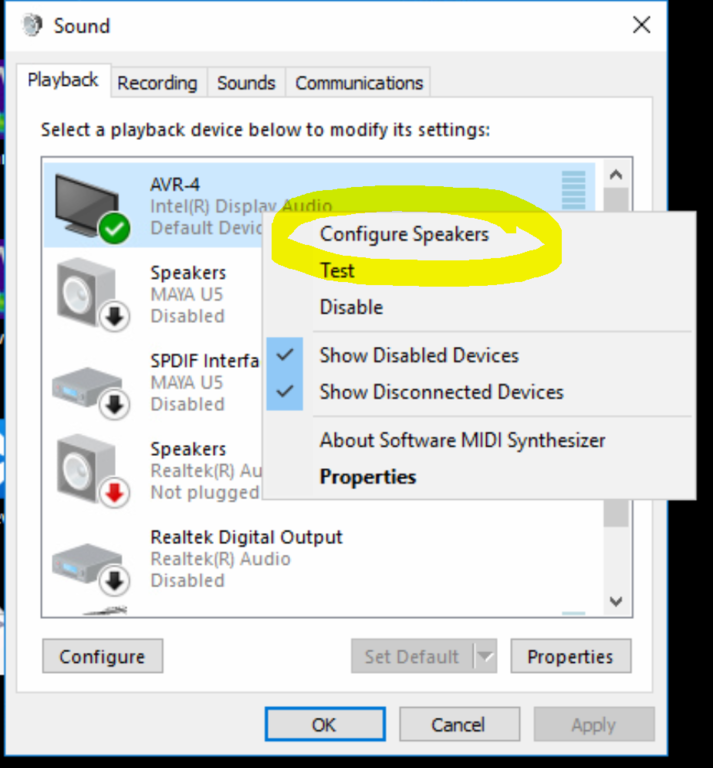
In a recent Windows 10 update, they hid this screen and it is no longer available through the “Start” menu. Instead, you need to open the Control Panel and select the “Sound” menu item.
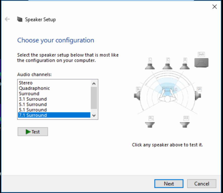
We choose the 7.1 mode:
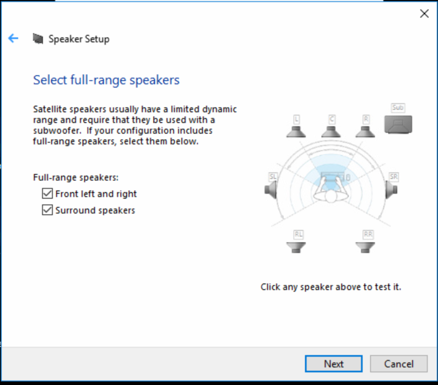
We select all available speakers:
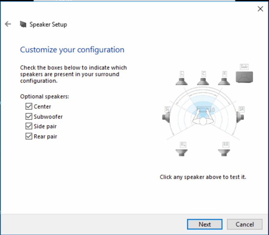
We note that all columns are full-range columns:
Once we’re done with this screen, we’re back to the soundcard settings. We choose the 24-bit or 32-bit mode:
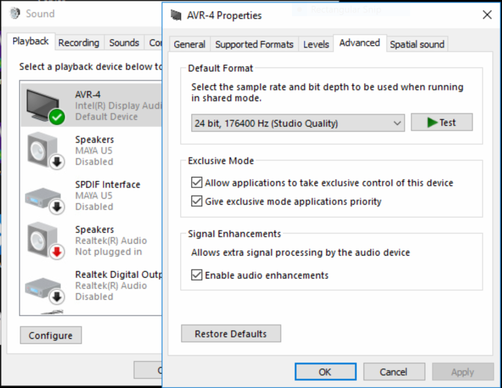
The sampling rate can be left as 44100 or 48000.
APO Equalizer stores the current configuration in the config\config.txt file in the application folder. So when you installed EqualizerAPO to your C:\ drive, you will find the file at this address: C:\EqualizerAPO\config\config.txt. We open it in the text editor. Normal Notepad is enough, but only allows one change to be undone, so I recommend either Word or Notepad ++.
You can also use the interactive editor built into EqualizerAPO, but I personally recommend changing the text files. With multi-channel fixtures, it’s easier to work with text than with a graphical interface.
This is an example configuration file:
# A comment
Preamp: -0.1 dB

Channel: 1
Preamp: -1 dB

Copy: 1=L 2=R 5=0.5*L+0.5*R 6=0.5*L+0.5*R 7=L 8=R

Channel: 1
Delay: 0.56 ms
Convolution: arcam-mids-176-70k.wav
Include: left-eq-arcam.txt

Channel: 2
Delay: 0.56 ms
Convolution: arcam-mids-176-70k.wav
Include: right-eq-arcam.txt

Channel: 5
Convolution: arcam-subs-176-70k.wav
Filter: ON HP Fc 18 Hz
Filter: ON HP Fc 18 Hz
Filter: ON HP Fc 18 Hz
Filter: ON HP Fc 18 Hz
Include: sub-eq-arcam-positive-polarity.txt

Channel: 6
Convolution: arcam-subs-176-70k.wav
Filter: ON HP Fc 18 Hz
Filter: ON HP Fc 18 Hz
Filter: ON HP Fc 18 Hz
Filter: ON HP Fc 18 Hz
Include: sub-eq-arcam-positive-polarity.txt

Channel: 7
Delay: 0.08 ms
Convolution: arcam-horns-176-low-pass-70k.wav
Include: left-eq-arcam.txt

Channel: 8
Delay: 0.08 ms
Convolution: arcam-horns-176-low-pass-70k.wav
Include: right-eq-arcam.txt
The configuration file contains a set of commands. One per line. We don’t write two commands on one line.
Here you will find documentation for all available commands: https://sourceforge.net/p/equalizerapo/wiki/Configuration%20reference/
Here I will describe only the most important options.
Comments.
When we want to disable a command or remember why there is another command, we write comments. We put # and all symbols will be ignored after that.
Preamp: -2.5 dB
Lowers the volume by 2.5 dB. You can also raise the volume, but I do not recommend doing it so as not to overdrive it by accident.
Delay: 0.4 ms
This gives a delay of 0.4 ms.
Convolution: wave file
Applies the FIR filter. I recommend mono 32-bit float files.
Filter: ON HP Fc 18 Hz
12dB / Octave Butterworth High Pass Filter.
Filter: ON HP Fc 18 Hz
Filter: ON HP Fc 18 Hz
Produces a 24dB / Octave Linkwitz-Riley high pass filter. It will be an IIR minimum phase filter, similar to the one we can do with coils and capacitors.
Filter: ON LP Fc 300 Hz
Filter: ON LP Fc 300 Hz
Linkwitz-Riley low pass filter 24 dB / octave.
Include: file.txt
Loads the REW upgrade file.
Channel: 1 2
Sets the channels to which the next commands belong. E.g:
Copy: 1=L 2=R 5=L 6=R
Copies channels. Also available math operations. E.g.
Copy: 1=L 2=R 4=0.5*L+0.5*R 5=L 6=R
This is an example of a configuration file for a 2-way column with a split frequency of 2000 Hz:
Copy: 1=L 2=R 5=L 6=R

Channel: 1 2
Filter: ON LP Fc 2000 Hz
Filter: ON LP Fc 2000 Hz

Channel: 5 6
Filter: ON HP Fc 2000 Hz
Filter: ON HP Fc 2000 Hz
When we have the receiver connected, the signal for the bass speakers will be on the front channels, and for the tweeters on the surround. We can run, for example, Foobar or YouTube and listen to music.
Active Loudspeakers “Quickly”
I started my adventure with active filters from the conversion of passive factory-made loudspeakers. First, I connected them via bi-amp and corrected the phase of the built-in filters using a set of FIR filters. Then I tried to bypass passive filters and connected the woofer and midrange driver straight to the amplifier and set up the filters on the computer. I brought the signal cables into the speaker enclsoure through the bass-reflex vent. I didn’t have the most expensive speakers. The difference between passive filters and an active crossover without passive components was drastic.
I will describe the entire loudspeaker configuration process step by step. I will describe only available options. I will not describe the choice of the particular frequency or filter because it is a very complicated topic. Here you will find only a guide through options of the EqualizerAPO software.
We will need Room EQ Wizard, a measuring microphone and a tripod.
Step 1
We mount the microphone on a tripod and set the tripod at the listening position. The microphone must be about in the place of the listener’s head.
Step 2
At the beginning, we check that we have connected the speakers correctly. We check the speaker phase.
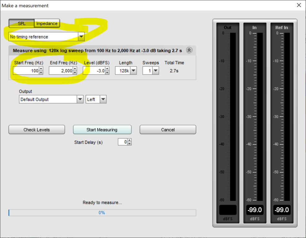
We switch to REW. We press Measure. We set the parameters as in the picture.
We save. We switch to the Impulse cartridge. The first must be a hill, not a hole.
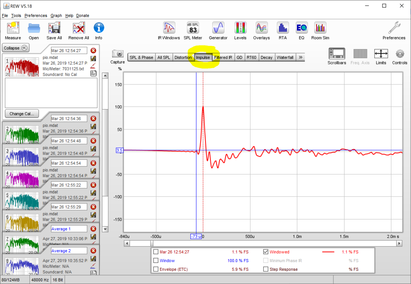
Here we see the left channel woofer pulse. When we have a dimple instead of a hill, we made a mistake when connecting the loudspeaker. We turn the wires when we have a dimple. We also check the right channel woofer.
After the woofers, we check the tweeters. We enter the command Copy.
Copy: 1=C 2=C 5=L 6=R
This command routes the left and right channels to the tweeters. We repeat the measurements as above and check that we have connected the tweeters correctly.
Once we have made sure that all speakers are properly connected, remove the “Copy” command and proceed to the next step.
Step 3
We start by setting speaker delays. We remove everything from the configuration file and enter:
Copy: 1=L 2=C 5=R
This setup copies the left channel to the left channel woofer and the right channel to the left channel tweeter as well. This is needed to measure the woofer delay relative to the left channel tweeter.
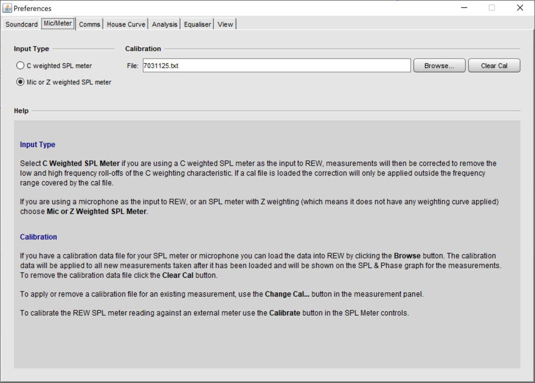
We run Room EQ Wizard (hereinafter “REW”). When we use the miniDSP microphone, the application will suggest to load the calibration file. When we have a different microphone, press the Preferences - Preferences menu. Put on the Mic insert and select the calibration file.
We set a small volume on the amplifier. Press the Measure button in the upper-left corner and choose the options as in the picture.
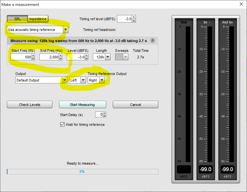
Select the “Use Acoustic Timing Reference” option. We choose frequencies from 100 to 2000. We measure the left channel with respect to the right one.
Press the button “Check Levels”. After measuring the volume level, REW will write if the volume is sufficient. When the volume is high enough, press “Start Measuring”. We hear a high-pitched screech followed by a “chuck” and see the measurement result for the woofer. On the left side we see a delay for the woofer. When the number is positive, we need a tweeter retarder. When the number is invalid, we need to delay the woofer.
We enter the delay in the configuration file:
Copy: 1=L 2=C 5=R

Channel: 1
Delay: 0.08 ms

Channel: 2
Delay: 0.08 ms
We repeat the measurement to make sure that we set the delay correctly. When the result is 0.02 ms, no more delays are required.
Step 4
We enter the frequency divisions to the configuration file. For example, split with a 4th order Linkwitz-Riley filter at 2000 Hz:
Copy: 1=L 2=R 5=L 6=R

Channel: 1 2
Filter: ON LP Fc 2000 Hz
Filter: ON LP Fc 2000 Hz

Channel: 5 6
Filter: ON HP Fc 2000 Hz
Filter: ON HP Fc 2000 Hz
Press the Measure button in the upper-left corner and choose the options as in the picture: * No timing references. * From: 20 To: 20000
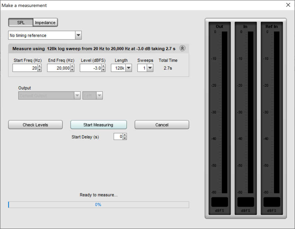
- Press the “Start Measuring” button. We hear a chirp and see the measurement result for the left channel. We measure the right channel.
- Move the tripod with the microphone forward by 5-10 cm. We measure the left channel, then the right channel.
- We raise the microphone by 5-10 cm and make two measurements. First left, then right.
- We shift 5-10 cm back and make two more measurements. After all, we have 8 measurements.
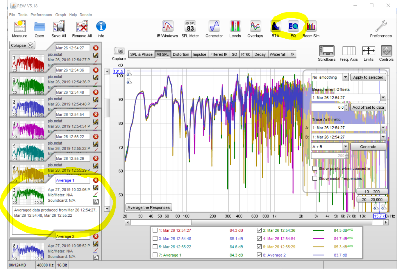
We switch to the “All SPL” cartridge. Press “Controls” in the upper right corner and choose “No Smoothing”, Apply To Selected. We hide the right channels. We press Average the Responses.
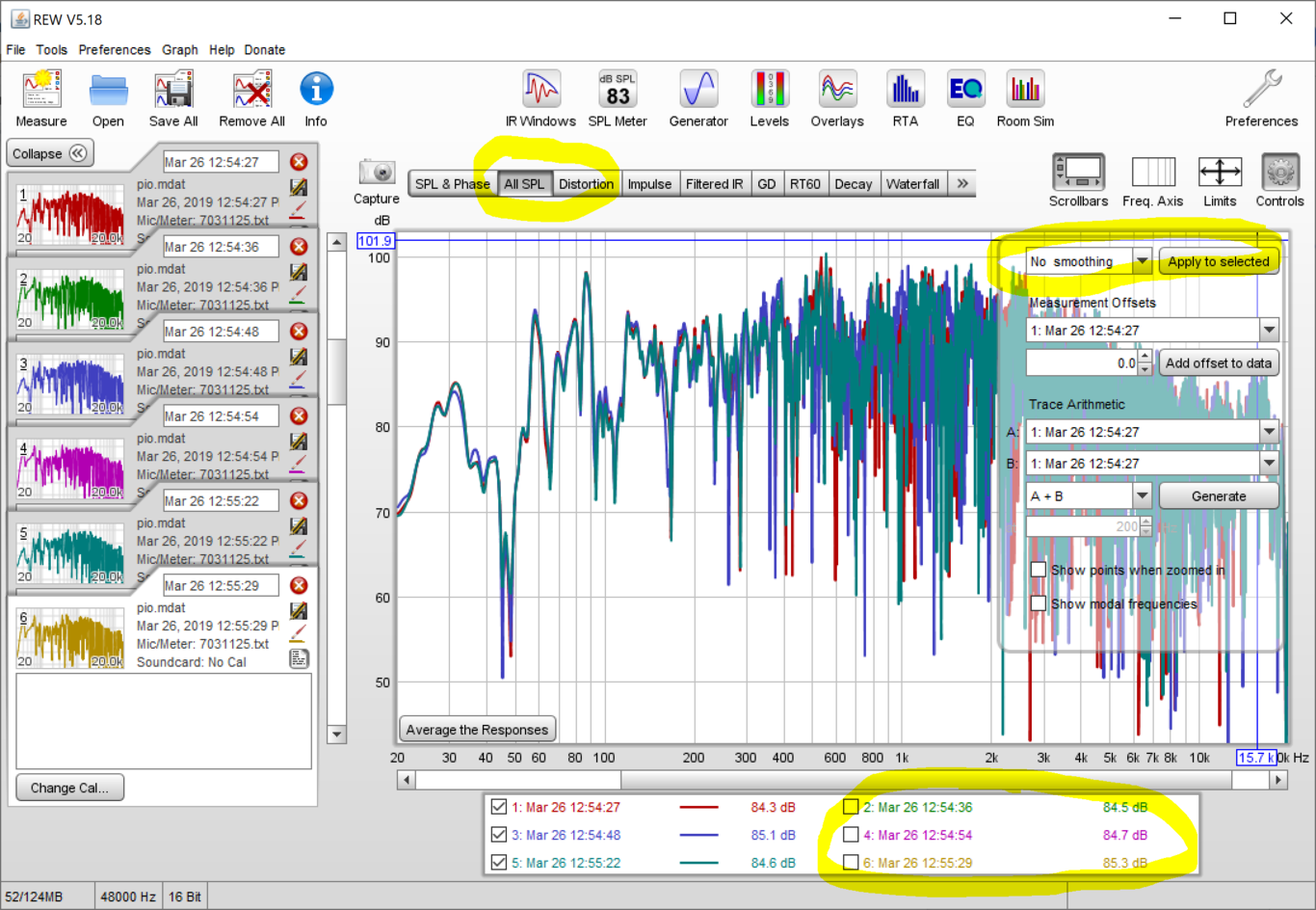
We get the average of the left channel measurements. Right-click and choose Toggle Responses. Then again Average the Responses. We get the mean of the right channel.
Step 5
Select Average 1 in the list on the left and hit the EQ button at the top.
We see a window. On the right side we choose:
Equalizer: Generic
Target Settings:
   Speaker Type: Full Range
   LF Cutoff: 10
   LF Rise Start: 200
   LF Rise End: 20
   LF Rise Slope: 2 (zależy od pokoju i życzeń)
   HF Fall Start: 200
   HF Fall Slope: 0.85 (zależy od pokoju i życzeń)
   Target Level: Set Target Level

Filter Tasks:
   Match Range: 20-20000
   Individual Max Boost: 0
   Overall Max Boost: 0
   Flatness Target: 3
We press “Match Response To Target” button. The application calculates filters. Press “Export Filter Settings To Text” and save the file in the EqualizerAPO configuration folder next to the config.txt file with the name left-eq.txt
Select the Average 2 measurement, press EQ. We repeat the parameters, but set the Target Level the same as for the left channel. We press “Match Response To Target”. We save the file with the name right-eq.txt
We change the configuration file:
Channel: 1
Include: left-eq.txt

Channel: 2
Include: right-eq.txt

Copy: 1 = L 2 = R 5 = L 6 = R

Channel: 1 2
Filter: ON LP Fc 2000 Hz
Filter: ON LP Fc 2000 Hz

Channel: 5 6
Filter: ON HP Fc 2000 Hz
Filter: ON HP Fc 2000 Hz
We do test measurements of the left and right channels. The frequency response has to look much more even than the “Average 1” measurement.
Now we can start playing and listen to some music. The columns are ready.